The automatic fire alarm system is generally set at industrial and civil construction sites, and constitutes a complete building fire protection system together with other fire classification equipment such as an automatic fire extinguishing system, an evacuation guidance system, a smoke control system, and a fire separation system. The automatic fire alarm system consists of a fire detection and alarm system, a fire-fighting linkage control system, a flammable gas detection and alarm system, and an electrical fire monitoring system.
First, fire detection and alarm system
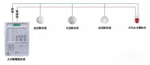
The fire detection and alarm system is composed of a fire alarm controller, a trigger device and a fire alarm device. It can timely and accurately detect the initial fire of a protected object and make an alarm response to inform the personnel in the building that the fire has occurred, thus making the building The personnel in the company have enough time to evacuate to a safe area when the development of the fire spreads to a level that endangers the safety of life. It is the most basic building fire protection system that ensures the safety of people's lives.
The composition of the fire detection and alarm system is shown in the figure.
Second, fire-fighting linkage control system
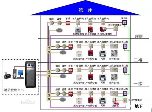
Fire-fighting linkage control system consists of fire linkage controller, fire control room graphic display device, fire electrical control device (fire shutter controller, gas fire control controller, etc.), fire electrical device, fire linkage module, fire hydrant button, fire emergency broadcast equipment , fire-fighting phones and other equipment and components.
In the event of a fire, the linkage controller accurately sends the linkage control signal to the fire control pump, spray pump, fire door, fire damper, anti-exhaust valve and ventilation and other fire fighting equipment according to the set control logic, and completes the fire extinguishing system and evacuation guidance system. The control functions of other fire-fighting related equipment such as smoke prevention systems, smoke control systems, and fire shutters will be fed back to the fire control room and displayed when the fire fighting equipment is activated.
Monitor the operational status of the building's firefighting facilities, that is, receive fire information or other triggers and input information from fire-fighting-linked field devices and other systems outside the fire automatic alarm system. Through the transmission equipment, the fire alarm signal and other relevant information issued by the fire alarm controller are transmitted to the building fire protection facility and the fire safety management remote monitoring system.
The composition of the fire-fighting linkage control system is shown in the figure.
Third, flammable gas detection and alarm system
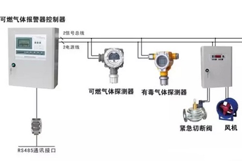
The flammable gas detection and alarm system is composed of combustible gas alarm controller, combustible gas detector and fire alarm. It can alarm in advance if the concentration of flammable gas leaks below the lower explosion limit in the protection zone, so as to prevent the flammable gas from leaking. The occurrence of fire and explosion accidents. The flammable gas detection and alarm system is an independent subsystem of the fire automatic alarm system and belongs to the fire warning system.
The composition of the flammable gas detection and alarm system is shown in the figure.
Fourth, electrical fire monitoring system
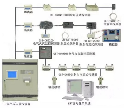
The electrical fire monitoring system consists of an electrical fire monitor and an electrical fire monitoring detector. It can provide an alarm in the event of an electrical fault and a certain electrical fire hazard, alerting professionals to eliminate electrical fire hazards, and early prevention of electrical fires. The occurrence of electrical fires. The electrical fire monitoring system is an independent subsystem of the fire automatic alarm system and belongs to the fire warning system.
The composition of the electrical fire monitoring system is shown in the figure.
Wiring requirements
Before wiring the automatic fire alarm system, the requirements of the design documents shall be checked to check the materials. The types and voltage levels of the conductors shall meet the requirements of the design documents; and the wiring shall be carried out in accordance with the following requirements.
1. The wiring of the automatic fire alarm system shall comply with the provisions of the national standard "Code for Acceptance of Construction Electrical Installation Engineering Quality" (GB50303-2015). The automatic fire alarm system shall be separately wired. Lines with different voltage levels and different current categories in the system shall not be placed in the same slot or in the same slot of the slot. The wiring in the pipe or in the trunk shall be carried out after the completion of construction plastering and ground works. There shall be no accumulation of water or debris in the pipe or in the trunk.
2. There should be no joints or kinks in the pipe or in the raceway. Wire connectors should be soldered in the terminal box or connected by terminals. The line leading from the junction box, trunking, etc. to the detector base, control equipment, and speaker shall not exceed 2m in length when metal hose is used for protection. Pipes and pipes that are laid in dusty or wet places must be sealed.
3. When the pipeline exceeds the following length, the junction box should be installed at the convenient wiring area:
(1) When the length of the pipe exceeds 30m, there is no bending;
(2) When the length of the pipe exceeds 20m, there is 1 bend;
(3) When the length of the pipe exceeds 10m, there are 2 bends;
(4) When the pipe length exceeds 8m, there are 3 bends.
4. The metal tube is put into the box. The outer side of the box should be sleeved and locked. The inner side should be equipped with a protective mouth. When laying in the ceiling, the inner and outer sides of the box should be sleeved and locked. Plastic tube into the box should take the appropriate fixed measures. When laying pipes and trunkings of different types, separate fixtures or supports shall be used for fixation. The diameter of the hanger for hoisting troughs or pipes should not be less than 6mm.
5. When laying the wire trough, set the hanging point or fulcrum at the following locations:
(1) The beginning of the trunking, terminal and joints;
(2) 0.2m away from the junction box;
(3) slot or corner;
(4) The straight section is not more than 3m.
6. The slot interface should be straight and tight, and the slot cover should be complete, flat and free from warping. When installing in parallel, the slot cover should be easy to open. Pipes passing through deformation joints (including settlement joints, expansion joints, seismic joints, etc.) of buildings shall be provided with compensation measures. The two sides of the conductors crossing the deformation joints shall be fixed with appropriate allowances.
7. Automatic fire alarm system After the conductors are laid, measure the insulation resistance of each loop conductor to the ground with a 500V megohmmeter, and the insulation resistance value should not be less than 20 MΩ. Wires in the same project should be selected according to different uses to distinguish different colors, the same purpose wire color should be consistent. The positive line of the power cord should be red, and the negative should be blue or black.
Their rollers and the outer wheels are arranged in a right angle intersecting intersecting. They can bear the load from all directions at the same time (such as axial, thrust or momentum hormones, etc.). Because of the linear contact between the roller and the track surface, the possibility of the axis to bear the load and the elastic deformation is very small. This type of bearing is widely used in industrial robots, working machines and medical facilities. It needs high rigidity, high speed and high speed to ensure precise occasions.
In cross roller bearings, cylindrical rollers are perpendicular to each other through spacer retainers on the top, so 1 cross roller bearings can bear all loads of radial load, axial load and torque load. Ring size is the minimum limit of miniaturization, especially very thin type is small size close to the limit, and has high rigidity, so the most suitable for use in industrial robot joint or rotating parts, machining center machine rotary table, hand rotating parts, precision rotary table, medical machine, metering device, IC manufacturing equipment etc.

1. Excellent rotation accuracy
The inner structure of the Cross Roller Bearing is arranged in 90 degrees perpendicular to each other by the roller.
The roller is equipped with a spacer or isolation block between the rollers to prevent the rolling of the rollers from being examined each other. In addition, the phenomenon of roller contact or locking will not occur. At the same time, because the inner and outer ring is a segmented structure, the clearance can be adjusted, even if the preload is applied, high accuracy rotation motion can also be achieved.
2. Simplification of operation and installation
The outer ring or inner ring, which is divided into 2 parts, is fixed together after loading the roller and the holder, so the operation is very simple.
3. Bear large axial and radial load
The roller is arranged vertically through the spacer retainer on a 90 degree V groove rolling surface.
4. Greatly save the installation space
The size of the inner and outer ring cross Roller Bearing is miniature minimal, especially ultra-thin structure is small size close to the limit, and has high rigidity, so the most suitable for industrial robot joints or rotating parts, machining center of the rotary table, the robot rotating parts, precision rotary table, medical instrument IC, measuring equipment, manufacturing device widely used.
5. high speed ability
6. reducing shaft length and machining cost, thermal expansion leads to a limited change in geometric size.
7. the nylon separator is used, the moment of inertia is low, the starting torque is low, and the angle degree is easy to control.
8. optimization of pretightening force, large rigidity, high precision of guiding roller
9. carbon steel provides excellent impact resistance and surface abrasion resistance
10. simple but fully lubricated