Double Axle Type Trailer,2 Axle Trailer,Double Axle Farm Trailer,Four Wheel Trailer Tipper JINING TIANDE ENGINEERING MACHINERY CO.,LTD , https://www.tdgoldargo.com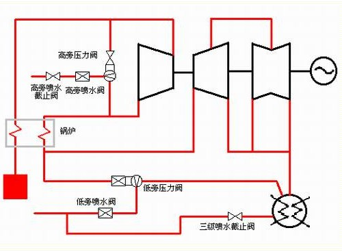
First, the basic situation of Siemens 50% bypass control system. (See Figure 1)
1, four adjustment doors:
High side pressure valve: with two motors of fast and constant speed;
High-side spray valve: only one motor but with constant speed and only
Fast opening function;
Low side pressure valve: with fast and constant speed two motors;
Low-side spray valve: only one motor, but with constant speed, and only
There is a quick opening function.
All fast acting motors complete within 4 to 5 seconds.
2, two stop valves:
High-side spray stop valve: only quick function, no valve position indication;
Coagulator inlet shutoff valve: also known as three-stage spray valve, only fast function, no
There is a valve position indication.
3, a power cabinet:
The control parts of all actuators are completed here. It provides power to actuators and also provides 380V.AC power to the control cabinet.
It accepts the instructions of the control cabinet, through a series of nodes that control the components, to power the power supply
Motor delivered to the actuator. There are ten control components in the control component.
4, control cabinet:
All control strategies are implemented here. It contains 3 levels of functionality:
Remote control level: All actuator stroke limit, midway switch node and torque limit are entered into the control cabinet, and various limit functions are realized through the relevant control components.
The power of the position transmitter is also provided here.
Location feedback is here to the operation panel.
Interlocking control level: The interlocking relationship between each valve, and the protection function, are also realized here. Most of the interlocking functions rely on the actuator's limit switch and the midway switch node as the interlocking basis.
Automatic Control Level: All functions for automatic shooting are implemented here. All measuring points are introduced into the control cabinet.
5, an operation panel:
The manual operation and manual/self switching of all actuators are completed here.
6, measuring point statistics: 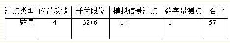
Siemens 50% bypass control system control cabinet includes 10 control components. Each control of each actuator speed (high speed and low speed) corresponds to a control component. Due to the difference in power and speed, many components cannot be used universally. However, in terms of its principle, it can be divided into two categories: the constant speed part and the high speed part. The principle of a single-speed motor is usually part of the speed. Here's a brief introduction to its working principle: 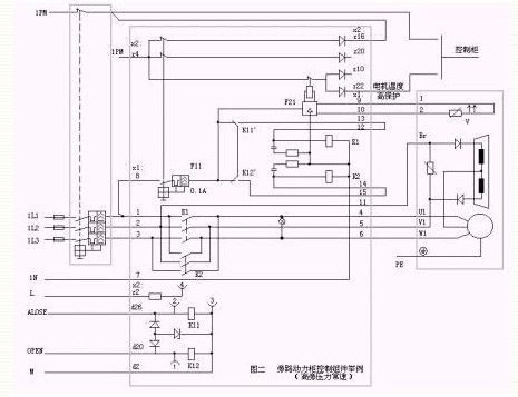
1, constant speed part: (Figure 2)
The 3L+ and M at the bottom left of the control unit are supplied with 24V DC power from the control cabinet. The control signal enters the K11 or K12 relay in the control module. K11 and K12 drive the K1 or K2 relay through K11 and K12. The K1 or K2 relay controls the 380V AC power to drive the actuator. The three diodes around K11 and K12 are used as limiter circuit protection relays, and the RC circuit around K1 and K2 is also used as protection relay. When the actuator switch is in position, the actuator's internal limit switch is activated, and the action signal is sent to the control cabinet. The control cabinet interrupts the switch command and releases the relay K1 and K2 so that the output power of the control module is inhibited and the actuator stops acting. .
At the same time, the component F21 receives the motor temperature signal from the actuator varistor. When the motor temperature is too high, F21 activates, so that the z22 terminal is high and output to the control cabinet. Therefore, the internal of the control cabinet interrupts the output of the operation instruction. The actuator stops operating.
2, high-speed part: (Figure 3)
The high-speed part of the control unit has little difference with the normal speed part. We introduce different parts of it. 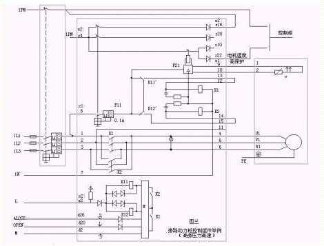
When the switch command comes to the control unit, relays K1 and K2 are actuated directly by a control module #. K11 and K12 together accept a signal that is 24V DC power. What I think it means is that K11 and K12 are always in action so that K11` and K12` can provide 220V power to K1 and K2. When the motor is overheating, K11` and K12 are disconnected from the power supply to achieve temperature protection.
Therefore, in the process of retrofitting high-speed control components, we must not think that L+ (plug number: x2 plug, z-column second) can use 24V DC power supply for this terminal. We must provide a 24V supply terminal for L+. DC power supply, otherwise it is possible that the high speed motor will not operate.
During the transformation process, we removed the operating signals and introduced them into the DCS. The actuators also introduce DCS into the limited bits. Various interlocking limits are added to the operating signals. Including the motor temperature signal also introduces DCS. When the motor temperature is high, the operation signal output is prohibited, so that the limit interlock protection function is achieved.
Third, the actuator part of the transformation:
1, travel limit
The implementation part of the transformation is mainly in the limit switch part. This section looks simple, but it is important. There have been some power plant's actuators that caused over-torque damage after the renovation.
Siemens bypass is a mature system, and the construction of each power plant is generally the same except that some details are not the same. S1 and S2 are torque switches, S3 and S4 are travel switches, and S7 and S8 are intermediate travel switches. Among them, the odd number restricts the closing direction, and the even number limits the opening direction.
From the above description it can be seen that all actuators have a quick function. There is no problem before the renovation. However, in DCS reconstruction, I thought that the scan cycle of the DCS system is not short enough. When an actuator is quickly full, the limit action is sent to the DCS to open an in-position signal, but if the DCS has not had time to scan this signal, wait until the scan, then the corresponding signal to terminate the fast open, this It is possible that the actuator may have opened too far. The direction is also similar. Especially at the end of each overhaul, from the commissioning of the unit to the start-up process, the bypass system repeatedly switches and tests, and it is very likely to cause damage to the actuator over-stroke over-torque. Therefore, before I overhauled, I repeatedly checked the DCS scanning cycle. As a result, our factory was 0.5 seconds and the problem was not too serious. In this regard, all manufacturers wishing to carry out the renovation must be given sufficient attention to this problem, otherwise there may be consequences of equipment damage.
The best solution is to add several dedicated control cards to the card provided by the DCS manufacturer. This control card can directly receive the limit signal of the actuator instead of entering the DPU operation. After the series of programs, the switch signal is directly output to direct the actuator action. Cards should respond much faster than the entire DCS system. In this way, the failure can be avoided most effectively.
In this overhaul, Xinhua manufacturers do not have such cards. We can only think of solutions from the S7 and S8 intermediate limit switches.
I think this way: When the actuator is closed to about 8%, adjust the limit switch S7 so that action; open to about 92%, adjust the S8 order action. This gives the DCS an opportunity for scan lag. However, the scan delay is uncertain. Latency is between zero and the entire scan cycle. If the lag time is very small, it may cause the switch to fail. As we all know, in the bypass system, if the valves are not opened properly, the problem is not significant; if the valves are not in place, it may cause leakage of the valve. If you want to solve this problem, only from DCS programming to find a solution. We can adjust the S1, S2 travel limit switches so that the valve opening moves at 0% or 100%. After the rapid action is over, if S1 or S2 has not acted yet, it means that the switch is not in place. At this time, a normal-speed action command is issued, and the normal-speed actuator is actuated until it is fully opened or closed. This satisfactorily solves the contradiction between fast and switch in place.
There is also a problem that the two cut-off valves have only the fast function and no normal speed function, and thus there is no way to achieve the problem of high-speed and constant-speed cooperation. We can take this approach: after the S7 or S8 action, if the operation instruction is still issued, then the instruction is forcibly interrupted, and then a 0.5 second wide pulse is issued every 0.5 to 1 second until the S1 or S2 action, and then Terminate the actuator completely. This will not break the shut-off valve.
2, brake part:
There are two main types of bypass actuator brakes in our factory. As shown in Figure 2, two brakes are used to brake in the half-wave circuit; the other is shown in Figure 4. All the wiring of the former braking method directly enters the control module, so there is no need to change the line and we will not introduce it here. Let's discuss the brake method and its control and interruption of the operation loop transformation shown in Fig. 4 below. In Figure 4, some unnecessary parts are not drawn, and the unpainted parts are the same as in Figure 2. 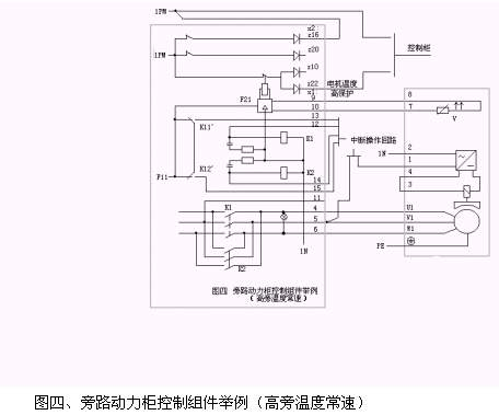
In Figure 4, the terminals x1:12, 13, 14, and 15 all enter the interrupt operation loop. When the high-speed command is issued, the contacts between 12 and 13, 14 and 15 are interrupted and the constant-speed motor cannot be operated. The operating principle of the inside of the operating loop is specifically interrupted because it does not involve the transformation part, so it will not be introduced here.
Fourth, after the transformation of the logic of the bypass:
Primary bypass system:
1. When the steam temperature is more than or equal to 350°C, turn off the side adjustment valve;
2. After the adjustment valve is automatically put on the side, the valve can be adjusted according to the setting value;
3. When the valve opening degree is adjusted to ≥ 2%, the desuperheating water adjustment valve can be opened;
4. When the MFT action (or oil switch trip) and load ≥ 30% rated load, the first bypass adjustment valve will execute the high-speed quick opening command;
5, When the bypass bypass valve is opened at high speed, it cannot be adjusted on the screen;
6. Whether the primary bypass adjustment valve is automatic or not, once the quick opening condition is established, the bypass bypass adjustment valve will realize the quick opening function;
7. When the oil switch is tripped (or steam temperature ≥350°C after one side), the low speed will be cut to manual.
8. Aside the adjustment valve opens unconditionally.
9. When the desuperheating water adjusting valve is in the automatic state, the valve can be adjusted according to the setting value.
Secondary bypass system:
1. When the steam temperature is higher than or equal to 180°C, close the two-way regulating valve and retreat to the manual state, and stop after 100 seconds.
2. When the opening of the desuperheating water adjusting valve is ≥ 5%, it is allowed to open the secondary bypass regulating valve;
3. When the three-stage desuperheating water stop valve is in place, it is allowed to open the secondary bypass regulating valve;
4. At the same time with the following conditions, realize the high-speed quick opening function of the secondary bypass adjustment valve.
Two side desuperheating water adjustment valve opening ≥ 5%;
After the steam temperature is less than or equal to 160 °C;
Before the side of the steam pressure ≥ 4Mpa;
Vacuum protection does not work.
5. When the bypass adjustment valve executes the quick opening command, the valve will exit the automatic and cannot be operated on the screen (ie: locking at normal speed);
Vacuum protection action, close the secondary bypass valve. If a quick open command is in progress, it will stop immediately and close the secondary bypass trim valve (normal speed).
6, After the secondary bypass pressure adjustment is the former value of temperature adjustment.
There are many important parts in the Siemens bypass system. For example, the interruption of the operating circuit, the motor overheat protection circuit, the power supply circuit, and so on, in particular, should pay attention to the debugging process after the transformation. Since in the course of this transformation, the above loop is not involved with respect to the control cabinet, it will not be described here. If readers are interested, they can contact the authors and discuss with each other.
It should be noted that the above transformation method should not be the only one. Perhaps the reader will have a better and more perfect method. Welcome to give more valuable opinions.
Siemens 50% bypass control system transformation
The application effect of Siemens 50% bypass control system in our factory has been very good, but because our factory carries on the DCS transformation, wants to introduce the bypass system into the DCS control, therefore must carry on the transformation to Siemens 50% bypass control system. After a major repair effort, we successfully completed the transformation task and successfully commissioned it once. Below I will make a technical summary of the transformation. Second, the control module principle and transformation: When the actuator is powered, one phase of the actuator motor is removed from the power cabinet terminal and enters the interruption circuit. After a middle contact, enter the actuator's brake. After rectification, it enters the brake coil, and the brake card springs up and the actuator can move.