Abstract : The method of live detection using zinc oxide surge arresters that can eliminate field interference under operating voltage has obvious advantages over DC leakage current testing under power outage conditions. This article mainly analyzes the effect of phase-to-phase capacitive coupling on leakage current and eliminates its effect. In order to make the zinc oxide surge arrester safe and reliable in the power system, the main contents of the LD/T596-1996 "Protective Test Regulations for Electrical Equipment" of the power industry standard for zinc oxide surge arresters are as follows: According to the "Regulations", preventive tests for zinc oxide surge arresters include DC leakage current tests under the conditions of power failure and live tests under operating voltage. However, when the operating voltage of the power system is high, and the number of lightning arresters in power plants (or substations) is large, it is very difficult to perform DC leakage current tests under power outage conditions. Therefore, more and more field electrification tests for zinc oxide arresters under operating voltage are being conducted. It is valued. 1 The importance of on-site live testing under oxidizing arrester operating voltage Oxidation arresters have been popularized and applied since the mid-1980s. In 1996, the “Regulations†promulgated by the State of the People's Republic of China clearly stipulated the on-site electrification tests of oxidative arresters under operating voltage. With the rapid development of computer technology and the continuous improvement of high-voltage electrical equipment testing, it has been proved that more items of oxidizing arresters have been tested (for example, the resistive current of the leakage current, the effective value of the capacitive current, the resistive current, and the capacitive current Component peaks, leakage current harmonic components, harmonic component power loss values, etc., can be more accurately reflected in the operation of the arrester. Table 1 shows a set of data for on-site inspection of a zinc oxide arrester in a 330kV substation. Table 1 Operational Test Results of a Zinc Oxide Surge Arrester in a 330kV Substation Detection time Voltage U Total current Io Resistive Current IR Power loss P A 2000.10.23 2001.4.1 2000.5.6 181.5 198.0 198.0 0.88 1.02 1.00 0.150 0.280 0.290 1.78 36.90 42.40 B 2000.10.23 2001.4.1 2000.5.6 184.5 194.7 198.0 0.84 0.89 0.91 0.112 0.150 0.160 11.08 20.10 21.10 C 2000.10.23 2001.4.1 2000.5.6 188.0 196.4 198.0 0.96 0.98 1.25 0.070 0.340 1.400 7.30 44.90 201.00 2 Impact of on-site interference test data Table 2 Field electrification test results of a zinc oxide arrester in a 500kV substation Installation Location Phase sequence Total current Io Resistive Current IR Power loss P A 500kV substation Main transformer side A B C 1.85 1.80 1.85 390 250 110 65.0 28.0 13.0 Reactor test A B C 1.70 1.86 1.74 440 280 100 81.4 36.4 0.87 From the data analysis in Table 2, it was found that for the normal zinc oxide surge arresters with the same model and same batch production lined up in the field, the leakage current Io value of the MOA of each phase was measured to have a small difference, and the resistive current IR and The power loss P has a significant difference, and is often centered on the data of the mesophase (phase B), while the phase A value is large and the phase C value is small. 2.2 Effect of Phase-to-Phase Capacitive Coupling on Test Data The schematic diagram of leakage current and phase-to-phase capacitance coupling when three-phase MOA is arranged in a straight line is shown in Figure 1. As can be seen from Figure 1, the leakage current measured at the bottom of the phase A phase is the sum of the current, ie, the actual leakage current generated by the operating voltage of the A-phase arrester, which can be decomposed into capacitive current and resistive current, ie, The capacitive interference current caused by the stray capacitance CAB between the phase B and phase A of the adjacent phase is negligible because the phase C is far from the phase A. Similarly, the leakage current measured at the bottom of Phase C can be similarly derived. Because the phase B position is centered, the capacitive coupling effects of A and C relative to each other are basically symmetric and the effects are negligible. The data from Table 2 can also illustrate this point. The phasor diagram of the effect of phase-to-phase coupling capacitance on the AA, B two-phase MOA leakage current is shown in Figure 2. 3 Measures to Eliminate the Effect of Phase Capacitive Coupling on Leakage Current Measurements Through the above analysis, two methods can be adopted to eliminate the influence of phase-to-phase capacitive coupling on the leakage current measurement, which may be referred to as hardware method and software method, respectively. 4. Conclusions The use of a zinc oxide surge arrester that eliminates on-site disturbances under the operating voltage detection method has obvious advantages over the DC leakage current test under power outage conditions. The on-site detection of the zinc oxide surge arresters can detect problems in a timely and accurate manner, which is of great significance for the safe and stable operation of the power system. Glass Microfiber Filter Paper of HEPA Grade (H10-H14)
HEPA Grade (H10-H14)
HEPA fiberglass filter media are comprised primarily of glass microfibers and are produced with a wet laid process similar to those used for the production of paper. It's an ideal raw material to produce air filters. It's efficiency ranges from H10-H14 with low pressure drop and good strength.
Fiberglass H14 Air Filter Paper,Fiberglass H13 Air Filter Paper,Fiberglass H12 Air Filter Paper,Fiberglass H11 Air Filter Paper,Fiberglass H10 Air Filter Paper,
Fiberglass Hepa Air Filter Core,Fiberglass H12 Air Filter Paper,Hepa Fiberglass Air Filter Media,Fiberglass Filter Media Hebei Fangyu Trade Co., Ltd. , https://www.filtersmaterial.com
Key words: Zinc Oxide arrester; Live test; Resistive current; Capacitive current; Capacitive coupling between phases
Arrester is one of the important electrical equipments in power system. It plays an important role in the safe operation of power system. The zinc oxide lightning arrester (MOA) is a new type of lightning arrester that is quite different from other types of arresters. Due to its obvious advantages in performance, it has been widely promoted and applied in power systems.
(1) When the DC leakage current is tested, the voltage U1mA at 1mA is compared with the initial value or the manufacturer's specified value, and the variation is not more than ± 5%. The leakage current at the voltage of 0.75U1mA should not be greater than 50μA.
(2) When the measured value of full current, resistive current or power loss under operating voltage is compared with the initial value, the monitoring should be strengthened when there is a significant change. When the resistive current increases by 1 time, the power failure should be detected.  project
Xiang Bie
(kV , valid value )
( mA, valid value)
(mA, peak )
(W)
After analyzing the data in Table 1, it is found that the resistive current Ir of the field C arrester exceeds 0.3 mA (peak), and the growth rate is very fast, which is 20 times the initial period of operation. Therefore, the phase arrester is determined to be out of operation and disassembled. Later, it was found that the condition of the arrester inside the phase arrester has been damp.
If the user stipulates in accordance with the "Regulations" that DC leakage current tests should be conducted under conditions of blackout before the thunderstorm season each year, the defects of the C phase arrester may not be discovered in time, and the consequences may be disastrous. Therefore, it is of great significance to live electrification test of oxidizing arrester operating voltage!
2.1 Analysis of MOA field electrification test results With the development of high-voltage electrical equipment testing technology, the principle of field electrification test of zinc oxide arrester is not difficult. However, the field test shows that there is a large deviation in the test data. Table 2 shows the field electrification test results of a zinc oxide arrester in a 500kV substation.
( mA, valid value)
( μ A, peak )
(W, average ) 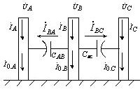
Fig.1 Leakage current and phase-to-phase capacitive coupling when three-phase MOA is aligned
In the field test, the capacitive current component of the MOA leakage current is the main component, while the resistive current component occupies a small proportion; due to the interferential capacitive coupling generated by the phase current is not large, so its effect on the capacitive current component is very Small, but the impact on the resistive current component is greater (the impact on power loss is also greater). Analyzing the phasor relationship of the MOA's electrical quantities shown in Fig. 2, we can see that the B-to-A-phase interference causes the leakage current ratio at the bottom of the A-phase to be reduced by the power factor angle of φ, which is relative to the C-phase interference and makes the C-phase bottom measurement. The power factor angle of the leakage current ratio is increased by φ; that is, the interference of B with respect to the A and C phases increases the resistive current component of the leakage current measured at the bottom of the A phase, and makes the leakage current resistance measured at the bottom of the C phase. The sexual current component is reduced. 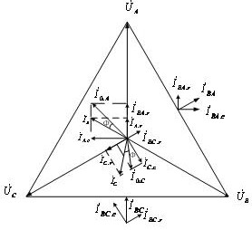
Fig. 2 Phasor diagram of influence of phase coupling on leakage current measurement
1. Hardware method: Metal foil electrode is attached to the outer porcelain sleeve of the tested MOA, and the influence of the inter-phase coupling capacitance on the leakage current measurement is shielded. 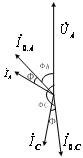
Fig. 3 Calculate the phasor diagram with the corrected power factor angle φ
2. Software method: Take the voltage signal of the voltage transformer of the phase A phase and the leakage current signal of the two phases A and C, and measure the phase angles φA and φC, respectively. From Fig. 3, it can be seen that φC-φA = 1200 + 2φ yields φ = (φC-φA - 1200)/2. Correct the power factor angle by the software of the test instrument so that the A-phase power factor angle = φA + φ and the C-phase power factor angle = φC-φ. Then the software can calculate the formula to eliminate the MOA leakage current and the components of the coupling capacitors. influences.
Obviously, the "software approach" is safe, simple and reliable, and it has been widely used in the field.
Hepa Air Filter Media


