1.75 A buffer is a part of the buffers-and-chain coupling system used on the railway systems of many countries, among them most of those in Europe, for attaching railway vehicles to one another. Rail Buffer,Train Buffer Stop,Sliding Type Rail Buffer,Hydraulic Sliding Type Rail Buffer Shenyang Lubang Railway Maintenance Machinery Co.,Ltd. , https://www.srmfrailwayequip.com
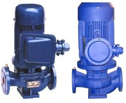
The YG series pipeline centrifugal oil pump is a product developed by the technical personnel of the unit. It was selected by water pump experts in the United Nations and adopts the hydraulic model and performance parameters of the IS centrifugal pump. This pump is designed based on a general vertical pump and has evolved into various types such as hot water pumps, high-temperature pumps, corrosive chemical pumps, and oil pumps based on the ISG type.
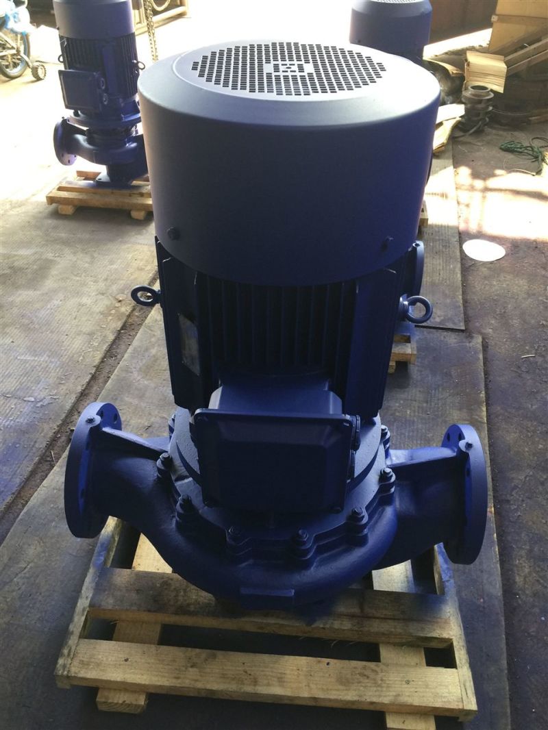
The YG vertical pipeline oil pump features:
1. The pump has a vertical structure with the same diameter and diameter, and it is located on the same center line. It can be installed like a valve in the pipeline. Its compact design saves space and reduces building investment, making it suitable for outdoor use;
2. The impeller is directly mounted on the motor's extension shaft, resulting in a short axial dimension and a compact structure. The pump and motor bearings are arranged reasonably to effectively balance the radial and axial loads during operation, ensuring stable performance and low vibration noise;
3. The shaft seal uses mechanical seals or combinations, featuring imported titanium alloy rings, medium-high temperature resistant mechanical seals, and hard alloy materials for excellent wear resistance and sealing performance, which significantly increases the service life of the mechanical seal;
4. Installation and maintenance are convenient, as there is no need to dismantle the pipeline system. Simply remove the pump joint nut to extract all rotor components.
The YG vertical pipeline oil pump is suitable for conveying media without solid particles, such as gasoline, kerosene, diesel, and other petroleum products, with a temperature range from -20°C to +120°C. If the transported medium has a temperature above 120°C or contains small amounts of particles, high-temperature or chemical pump structures should be selected.
The working conditions of the YG vertical pipeline oil pump include:
1. Suction pressure ≤1.0MPa, or pump system working pressure ≤1.6MPa, meaning that the sum of the suction pressure and head is ≤1.6MPa. The static pressure test pressure is 2.5MPa. Please indicate the system working pressure when ordering. If the system working pressure exceeds 1.6MPa, it should be specified at the time of ordering so that the over-flow parts and connections of the pump are made of cast steel material during manufacturing;
2. Ambient temperature <40°C, relative humidity <95%;
3. The volume of solid particles in the medium to be transported does not exceed 0.1% of the unit volume, and the particle size is >0.2 mm.
Note: If the medium contains small particles, please specify when ordering, so that the manufacturer can install a wear-resistant mechanical seal.
Â
Â
Â
(m)
(%)
(r/min)
(kw)
(m)
m3/h
L/s
15-80
1.5
0.42
8
34
2800
0.18
2.3
20-110
2.5
0.69
15
34
2800
0.37
2.3
20-160
2.5
0.69
32
25
2900
0.75
2.3
25-110
4
1.11
15
42
2900
0.55
2.3
25-125
4
1.11
20
36
2900
0.75
2.3
25-125A
3.6
1.0
16
35
2900
0.55
2.3
25-160
4
1.11
32
32
2900
1.5
2.3
25-160A
3.7
1.03
28
31
2900
1.1
2.3
32-125
5
1.39
20
44
2900
0.75
2.3
32-125A
4.5
1.25
16
43
2900
0.55
2.3
40-100
6.3
12.5
54
2900
0.55
2.3
40-100A
5.6
1.56
10
52
2900
0.37
2.3
40-125
6.3
1.75
20
46
2900
1.1
2.3
40-125A
5.6
1.56
16
45
2900
0.75
2.3
40-160
6.3
1.75
232
40
2900
2.2
2.3
40-160A
5.9
1.64
28
39
2900
1.5
2.3
40-160B
5.5
1.53
24
38
2900
1.1
2.3
40-200
6.3
1.75
50
33
2900
4.0
2.3
40-200A
5.9
1.64
44
31
2900
3.0
2.3
40-200B
5.3
1.47
36
29
2900
2.2
2.3
40-250
6.3
1.75
80
28
2900
7.5
2.3
40-250A
5.9
1.64
70
28
2900
5.5
2.3
40-250B
5.5
1.53
60
27
2900
4.0
2.3
40-100(I)
12.5
3.47
12.5
62
2900
1.1
2.3
40-100(I)A
11
3.305
10
60
2900
0.75
2.3
40-125(I)
12.5
3.47
20
58
2900
1.5
2.3
40-125(I)A
11
3.05
16
57
2900
1.1
2.3
40-160(I)
12.5
3.47
32
52
2900
3.0
2.3
40-160(I)A
11.7
3.25
28
51
2900
2.2
2.3
40-160(I)B
10.44
2.89
22
50
2900
1.5
2.3
40-200(I)
12.5
3.47
50
46
2900
5.5
2.3
40-200(I)A
11.7
3.25
44
45
2900
4.0
2.3
40-200(I)B
10.6
2.94
36
44
2900
3
2.3
40-250(I)
12.5
3.47
80
38
2900
11
2.3
40-250(I)A
11.6
3.22
70
38
2900
7.5
2.3
40-250(I)B
10.8
3.0
60
37
2900
7.5
2.3
40-250(I)C
10.0
2.78
52
36
2900
5.5
2.3
50-100
12.5
3.47
12.5
62
2900
1.1
2.3
50-100A
11
3.05
10
60
2900
0.75
2.3
50-125
12.5
3.47
20
58
2900
1.5
2.3
50-125A
11
3.05
16
57
2900
1.1
2.3
50-160
12.5
3.47
32
52
2900
3.0
2.3
50-160A
11.7
3.25
28
51
2900
2.2
2.3
50-160B
10.4
2.89
22
50
2900
1.5
2.3
50-200
12.5
3.47
50
46
2900
5.5
2.3
50-200A
11.6
3.25
44
45
2900
4.0
2.3
50-200B
10.6
2.94
36
44
2900
3
2.3
50-250
12.5
3.47
80
38
2900
11
2.3
50-250A
11.6
3.22
70
38
2900
7.5
2.3
50-250B
10.8
3.0
60
37
2900
7.5
2.3
50-250C
10.0
2.78
52
36
2900
5.5
2.3
50-100(I)
25
6.94
12.5
69
2900
1.5
2.3
50-100(I)A
22.3
6.19
10
38
2900
1.1
2.3
50-125(I)
25
6.94
20
37
2900
3.0
2.3
50-125(I)A
22.3
6.19
16
36
2900
2.2
2.3
Fitted at the ends of the vehicle frames, one at each corner, the buffers are projecting, shock-absorbing pads which, when vehicles are coupled, are brought into contact with those on the next vehicle. The draw chain used between each pair of vehicles includes a screw which is tightened after coupling to shorten the chain and keep the buffers pressed together. Such is known as a 'screw coupling'.